Banding can turn a clean digital print into a visibly striped surface. Under bright inspection light, solid blue areas may show pale horizontal lines, while skin tones can appear uneven. In high-speed production, these defects often emerge suddenly. A press may run correctly for hours, then reveal banding after a media change or temperature shift. What causes banding issues in high-speed digital printing? The answer usually involves several interacting factors, not one isolated fault.
Printhead alignment, nozzle performance, ink delivery, and scanning speed all deserve attention. A partially blocked nozzle can create repeated gaps across the image. Incorrect bidirectional registration may produce light and dark bands between passes. Media tension can also change during a long run, especially near the roll edges. Heat, humidity, and drying settings matter too. Small changes become visible quickly.
Start with evidence, not assumptions. Compare a nozzle check, a solid-fill test, and a calibrated reference file. Inspect the same area under consistent lighting. Check whether the bands follow the print direction or repeat at fixed intervals. This detail often narrows the cause. Experienced technicians also review maintenance records, ink temperature, encoder feedback, and recent firmware changes. Not every correction works immediately. That is normal.
A practical repair may require cleaning, alignment, speed adjustment, or media-tension correction. Test one variable at a time. Keep the results. Rushing can hide the real problem. This guide explains a reliable troubleshooting path, while acknowledging an uncomfortable truth: some banding requires service-level inspection when routine adjustments fail.
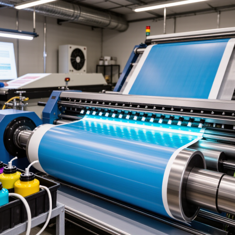
Banding in high-speed digital printing is easier to correct after its pattern is identified. I begin with controlled test charts at 600, 900, and 1,200 dpi. Each chart uses solid fills, fine lines, gradients, and repeated halftone blocks. Keep the substrate, ink load, curing, and press speed unchanged. Otherwise, the comparison becomes unreliable.
Look for the direction and rhythm of the defect. Regular horizontal stripes often suggest transport timing, feed variation, or scan synchronization. Vertical bands may indicate nozzle alignment, carriage behavior, or uneven ink delivery.
A repeating pattern across every color points toward mechanics or data processing. A defect limited to one channel deserves a separate ink or printhead check. Small differences matter.
Measure the patches under consistent viewing conditions. ISO 13655 provides a recognized framework for spectral measurement, including illumination and observer settings. It does not diagnose banding by itself. Use it to compare density, color differences, and variation between test areas. I once blamed the printhead after seeing dark stripes, but the real cause was unstable media tension. My first reading was wrong. Repeating the test at two speeds exposed the pattern. Record the dpi, speed, direction, substrate batch, and measurement results. A phone photograph can help, but it cannot replace instrument data. Some banding appears only at normal viewing distance. Test there too.
How to Fix Banding in High Speed Digital Printing
Banding often starts with a small printhead alignment error. At high speeds, that error becomes visible across wide areas. I have seen clean artwork produce uneven horizontal lines after a minor carriage adjustment. The first check should be a nozzle test, not a color profile change. Confirm that at least 99% of the nozzles are active before changing other settings.
Print a diagnostic pattern at the machine’s normal production speed. Inspect repeated gaps, misfired lines, and color separation with a magnifier. A nozzle count can look acceptable while several adjacent nozzles remain inactive. That cluster may create a visible stripe. Clean the affected head according to the equipment procedure, then print the test again. Check alignment in both the scan direction and media-feed direction. Even a small offset can cause overlapping dots to form bands.
Keep the media flat and tension steady. Temperature and ink viscosity also influence drop placement. Record each adjustment, including the time and test result. This makes troubleshooting more reliable. Do not assume one cleaning cycle solves everything. In my experience, repeated cleaning sometimes hides a mechanical problem. A loose mounting point, unstable airflow, or inaccurate feed calibration may still remain. If active nozzles fall below 99%, pause production and investigate before increasing speed. Slowing the press can reduce the symptom, but it does not repair the cause.
| Test Run | Print Speed (m/min) |
Print Resolution (dpi) |
Visible Banding (1–5) |
Active Nozzles (%) |
Printhead Alignment Offset (µm) |
Number of Passes | Corrective Action | Verification Result |
|---|---|---|---|---|---|---|---|---|
| Baseline A | 75 | 600 × 600 | 4 | 97.8 | +42 | 2 | Clean the nozzle plate and run a nozzle check | Not Acceptable |
| Baseline B | 100 | 600 × 600 | 5 | 96.9 | +58 | 2 | Inspect missing nozzles and reduce print speed for testing | Not Acceptable |
| Alignment Check | 75 | 600 × 600 | 3 | 98.7 | +18 | 2 | Perform bidirectional and horizontal printhead alignment | Needs Recheck |
| Nozzle Recovery | 75 | 600 × 600 | 2 | 99.1 | +16 | 2 | Complete approved purge and wipe cycle; repeat nozzle check | Pass |
| Fine Alignment | 100 | 600 × 600 | 2 | 99.3 | +7 | 2 | Apply fine alignment correction and verify carriage timing | Pass |
| High-Speed Trial | 125 | 600 × 600 | 2 | 99.2 | +6 | 2 | Maintain alignment settings and confirm stable media transport | Pass |
| High-Speed Trial | 150 | 600 × 600 | 3 | 99.0 | +9 | 2 | Check ink delivery stability and repeat the nozzle test | Needs Recheck |
| Final Verification | 125 | 600 × 600 | 1 | 99.5 | +4 | 4 | Use the verified alignment profile and four-pass production mode | Pass |
| Acceptance reference: Maintain at least 99% active nozzles, minimize printhead alignment offset, and confirm banding with a production-speed test on the actual substrate. | ||||||||
Banding often begins with unstable conditions, not a faulty printhead. Keep ink, media, and drying zones within ±2°C and ±5% relative humidity. Small shifts can change ink viscosity, paper moisture, and droplet spread. Measure conditions beside the press, not only near the building controls. The 2024 ASHRAE Handbook recommends stable indoor humidity management, commonly within 30–60% RH, while tighter production control improves repeatability. ISO 12647-8 also frames digital print quality as a controlled process, rather than a profile-only problem.
Watch the process closely. A cold ink line may produce uneven jetting during startup. Damp media can curl, stretch, or absorb ink unevenly. Excessive dryer heat may create gloss variation and shrinkage. Record room temperature, media temperature, dryer settings, nozzle checks, and density readings every shift. A practical target is 22°C ±2°C and 50% RH ±5%, adjusted after testing the actual substrate. This is not universal. I have seen “correct” settings fail when media acclimatization was skipped.
Tips: Let sealed media rest in the print room before opening. Place calibrated sensors at the feeder and delivery areas. Check ink viscosity after temperature changes. Clean or verify nozzles before increasing dryer power. If banding remains, reduce speed briefly and compare the pattern. That pause may reveal whether the cause is mechanical, thermal, or environmental. Perfect control is difficult, and the first diagnosis can be wrong.
At 75–150 m/min, banding often starts when web speed outruns drop placement. Each drop must land within a narrow timing window. A small delay can create visible light and dark stripes. Check the encoder signal, firing frequency, and transport speed together. Do not adjust only the ink settings. A stable web path matters just as much. Watch the substrate near the print zone. Vibration, edge curl, or uneven tension can shift the image between passes.
Use a measured speed profile instead of one fixed setting. Test at 75, 100, 125, and 150 m/min with the same artwork. Compare solid fills under consistent lighting. Record the band spacing and its direction. If spacing changes with speed, drop timing is probably involved. If spacing stays fixed, inspect mechanical pitch or transport components. In practice, the first correction is rarely perfect. I have seen operators reduce speed too quickly, hiding the symptom rather than fixing synchronization. That approach costs time later.
Tips: Calibrate the encoder before changing waveform settings. Keep web tension stable during acceleration. Use a simple grid and solid patch for testing. Inspect samples after they reach room temperature. Check nozzle health at every speed step. Leave a small speed margin below the failure point. A clean result at 150 m/min may still fail during a real roll change.
Banding often appears when ink laydown changes across the web or sheet. At high speed, small timing errors become visible stripes. Practical press evaluations should begin with a controlled uniformity test, not visual judgment alone. Print a solid patch across the full image width, including leading and trailing areas. Keep substrate, ink condition, curing, and press speed unchanged.
Measure the patch with a calibrated spectrophotometer under consistent lighting and measurement settings. Compare readings across the sheet, not only at the center. The acceptance target is ΔE00 ≤2 between corresponding locations. Density variation should remain ≤2% from the approved reference. Record temperature, humidity, line speed, and measurement direction. These details expose patterns that operators may miss.
If results fail, inspect nozzle timing, printhead alignment, media tension, and dryer balance. A loose tension setting can create repeating bands every few inches. Uneven curing may also shift density near the sheet edges. Recheck after one adjustment only. Changing several settings at once weakens the diagnosis. In some trials, visual banding disappeared while ΔE00 still exceeded two. That result deserves attention. The print looked acceptable, but the data disagreed. Repeat the test after production stabilizes, because the first sheet may not represent the entire run. Keep signed records of readings, images, and corrective actions for reliable process control.
Print test charts at 600, 900, and 1,200 dpi. Use solid fills, fine lines, gradients, and repeated halftone blocks. Keep speed, substrate, ink load, and curing unchanged. Horizontal stripes may indicate feed timing or scan synchronization. Vertical bands may suggest nozzle alignment or uneven ink delivery. Small differences matter.
It often points toward mechanical movement or data processing. Check media transport, feed calibration, and scan timing. A defect affecting one color needs a separate ink or printhead inspection. Do not change color profiles first. That can hide the real cause.
Measure patches under the same lighting and viewing conditions. Use consistent spectral settings for illumination and observer evaluation. Compare density, color difference, and variation between test areas. Instrument data is more reliable than phone photographs. Still, a photo can show visible stripes. It cannot prove the cause.
Confirm that at least 99% of nozzles are active. Print the diagnostic pattern at normal production speed. Inspect repeated gaps and misfired lines with a magnifier. Several adjacent inactive nozzles can create one broad stripe. Clean the affected head according to the equipment procedure. Then repeat the test.
Check alignment in both scan and media-feed directions. A small offset can make overlapping dots form visible bands. Inspect the printhead mount for looseness. Also check carriage movement and feed calibration. Slowing the press may reduce symptoms. It does not repair the cause.
Temperature changes can alter ink viscosity and droplet placement. Humidity changes can affect media moisture, stretching, and ink absorption. Keep production conditions near 22°C and 50% relative humidity. A practical tolerance is ±2°C and ±5% RH. These values require testing on the actual substrate. They are not universal.
Place calibrated sensors near the feeder and delivery areas. Building-control readings may not represent press-side conditions. Record room temperature, media temperature, and drying settings every shift. Check ink viscosity after noticeable temperature changes. The feeder may be colder. That detail is easy to miss.
Record dpi, speed, print direction, substrate batch, and measurement results. Include nozzle checks, density readings, cleaning actions, and adjustment times. Let sealed media acclimatize before opening it. Compare the pattern at normal viewing distance. I once blamed the printhead incorrectly. A second speed test revealed unstable media tension.
Banding in high-speed digital printing can result from unstable drop placement, misaligned printheads, inactive nozzles, or inconsistent interactions between ink, media, and drying conditions. To determine what causes banding issues in high-speed digital printing, begin with controlled test patterns at 600–1,200 dpi and evaluate them using ISO 13655 measurement methods. This helps distinguish horizontal, vertical, density, and repeating defects before corrective action is taken.
Next, align the printheads carefully and verify that at least 99% of nozzles are active. Keep ink temperature, media conditions, and drying performance stable, targeting variation within ±2°C and ±5% relative humidity. Web speed should also match drop placement behavior across operating profiles from 75 to 150 m/min. Finally, confirm print uniformity through objective measurements, aiming for a color difference of ΔE00 ≤2 and density variation of no more than 2%. This structured process helps reduce visible banding while improving consistency, productivity, and repeatability.

DD-Tech Print